SOCIETY OF AFRICAN EARTH SCIENTISTS WORKSHOP NOTES
CONTENTS
1. SOLAR PHOTOVOLTAIC ENERGY SYSTEM INSTALLATION
2. SOIL AND WATER CONSERVATION IN AFRICA
 SOLAR PHOTO VOLTAIC ENERGY SYSTEM INSTALLATION
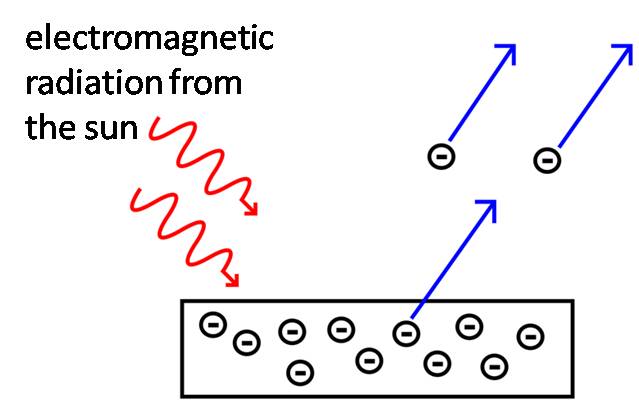
Photoelectric Effect
When electromagnetic radiation falls onto the surface of a
metal, it is observed that electrons may be ejected. This phenomenon is called the photoelectric
effect.
The effect was first observed in 1887 by a German scientist
named Heinrich Hertz .
In 1899 J. J. Thompson proved that electrons were being
emitted due to the action of electromagnetic radiation.
Then in 1905 Albert Einstein won the Nobel Prize for
explaining that electromagnetic radiation (for instance, common sunlight) is
formed by packets of energy called photons. To understand this is it helps to
think of these “packets” as containers (having no mass) which carry energy from
the source (the sun) to the metal surface.
Introduction to
Electricity
Consider two points, respectively the positive and
negative terminals of a battery, connected by a copper wire. An electric current flows through the wire
when there is an electrical potential difference between the two points.
A simple electric circuit illustrated below includes a battery, a fuse and a solar charge controller. To locate
the fuse to protect our solar charge controller, we place it on the positive wire leaving the positive terminal of the battery and leading to the solar charge controller, as this is the direction of the electric current. This is the case for any electrical device we wish to protect: the fuse is always located at the wire leading from the positive battery terminal to the device, as shown below. In our installation of a 24v solar photovoltaic system, we place a 20 amp fuse on the wire leading from the positive terminal of the battery to the charge controller. The 20 amp (A) charge controller is protected by a 20A fuse, which will break the circuit if a current greater than 20 A travels from the battery towards the controller.
A simple electric circuit illustrated below includes a battery, a fuse and a solar charge controller. To locate
 |
| Figure 2. Simple circuit consisting of battery, fuse and charge controller |
We move on to define basic concepts of electricity
which will be of relevance in our solar electricity installation.
i)
Electric Charge - The build-up of electricity.
In nature we witness an electric charge as a lightning strike. A battery stores
an electric charge. Batteries will be a
key component in our solar setup, as we wish to store up the energy we collect
from solar panels. Electric charge is measured in coulombs,
ii)
Electric Current - This is the flow of an
electric charge. Electric current is measured in amps (A).
iii)
Electric Potential – Refers to the potential
difference in electrical energy between two points, such as the positive and
negative terminals of a battery. It is measured in volts (v).
iv)
Relationship between volts, amps, ohms and
watts-hours
a.
Voltage (v) is a measure of potential difference
b.
Resistance (R) is a bit like friction - it is
the natural opposition to an electron flow found in a material. It is measured in ohms.
c.
As already noted above, current (I) is a measure of the flow of
electrons /electric charge in a circuit. It is measured in amps (A).
d.
Power (P) measures the rate at which electrical
energy is converted into work (whatever that work is: boiling a kettle,
operating a drill, etc.). It is measured in watts (W).
e.
Energy (E) refers to the capacity for work
is power x time and measured in joules
(1 watt/s), but usually shown as watts-hours or kilowatt-hours.
Important relations to note are
that
V = I R
(1)
P
= V I = I2 R (2)
How a Solar Panel
Works
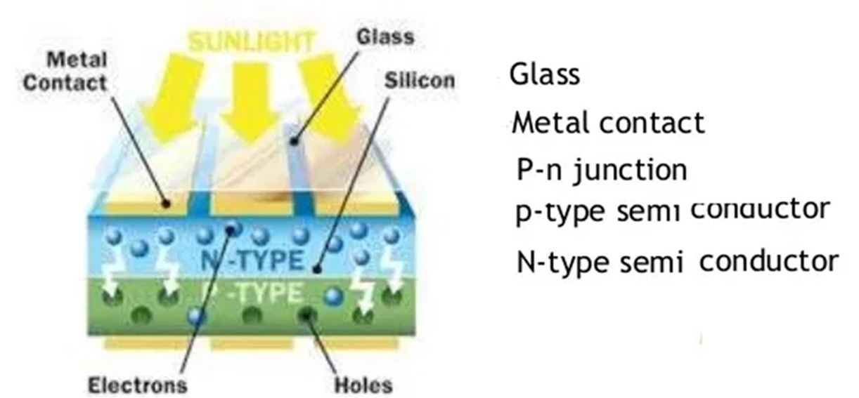
A solar panel consists of a grid of many singular solar
cells. Each cell consists of two semiconductor layers called P- and N-type
semiconductors, which are joined by conductive wiring. The N-type upper layer (blue colour layer,
in above figure) is pure silicon that has been mixed with negatively charged
phosphorous and so has an excess of electrons; whilst the lower layer (green layer above) is pure silicon that has
been mixed with positively charged boron, leading to a deficit in electrons (or
holes). By “doping” or adulterating the pure silicon with respectively
negatively or positively charged elements, a potential difference is created
between the two semiconductor layers so that one layer is relatively positively
(or negatively) charged in respect to the other. When light falls onto the
solar cell, the potential difference creates an electric field in the gap
between the two semiconductor layers, and a current flows from one layer of the
solar cell to the other, causing a positive charge to flow from the positive to
the negative terminal. The gap between the two layers is called the p-n
junction. The electric current actually flows in the opposite direction to the
electrons. Conceptually, the travel of
negatively charged electrons from the negative to the positive terminal is
equivalent to the travel of a positive charge from the positive to the negative
terminal.
Components of a Solar
Electric Energy System
The key components of a solar electric energy system demonstrated in the workshop are
- · Solar panels
- · Batteries
- · Solar charge controller
- · Pure sine wave power inverter
Having a pure sine wave inverter in place of a simple
inverter ensures that computer or other sensitive electronic equipment is
protected from fluctuations in voltage. The arrow in the diagram below
indicates the AC (alternating current) output from the power inverter to power
household appliances.

(Not to scale)
The above figure gives an outline of a 24v solar
photovoltaic system installation consisting of:-
- Two 12v and 150 W solar panels arranged in series to give a 24v solar panel array.
- Two 12v deep cycle batteries arranged in series to create a 24v battery bank
- A 2000W, 24v pure sine wave power inverter
- A 20 amps, 12v / 24v solar charge controller
- Accessories including, wiring, fuses and battery terminal clamps.
The materials listed above for our solar electric system can
be purchased at UK prices for under £1400 pounds sterling as at August 2013. Cheaper options are available to the buyer by, for instance, going without some of the capacity provided by 4 batteries in LIST A below, and instead making do with 2 batteries. Solar enthusiasts can purchase the bare necessities to begin with and add more capacity to their solar electric system as available funds dictate, by acquiring more battery capacity and/or adding solar panels to the array to generate more power.
We consider the details of installation for each of the four
main components.
 |
| Figure5. Two 12v, 150W solar panels connected in series |
Solar Panels
Solar panels can be arranged in an array by connecting in
series or in parallel. Which arrangement
we choose will depend on the capacity and voltage we wish to maintain for our
system.
Example: 24v series array formed by 2 x 12v solar panels
Series array - allows the panels to run at a higher voltage
A series connection between two solar panels is made by
connecting the positive terminal of one panel to the negative terminal of the
other panel. Two 12v solar panels
connected in series will give a 24v solar panel array. Similarly, three 12v
solar panels in series would give a 36v array; whilst four connected in series
would give us a 48v solar panel array.
Parallel array - more panels in parallel increases capacity
whilst voltage remains the same
A parallel connection between two solar panels is made by
connecting the positive terminal of one panel to the positive terminal of the
other (or negative terminal to negative terminal). Two 12v solar panels
connected in parallel will give us a 12v solar panel array. Similarly, three or
four or any number of 12v solar panels connected in parallel will give us a 12v
array of solar panels. Adding solar panels to the array in parallel will
increase the capacity of the array whilst maintaining the same voltage.
 |
| Figure 6. A 24v battery bank consisting of 2x12v batteries in parallel (close together on the right), connected in series to a single 12v battery (standing apart on left) |
Batteries
Just like the solar panels, batteries can be arranged in
series or parallel to increase or maintain voltage in accordance with system
requirements.
 |
| Figure 7. A 24v battery bank consisting of 2x12v batteries connected in series |
 |
| Figure 8. A 48v battery bank consisting of 4x12v batteries connected in series |
 |
| Figure 9. A12v battery bank consisting of 2x12v batteries connected in parallel |
 |
| Figure 10. A 12v battery bank consisting of 4 x 12v batteries connected in parallel |

 |
| Figures 11a and b. A 12/24v, 20 amp, solar charge controller |
Charge Controller
The charge controller controls the current into and out of
the batteries and helps to protect them, preventing them from overcharging or
discharging completely. Positive and negative terminals of the controller are
connected with respective positive and negative terminals of the solar panel
array and the battery bank.

 |
| Figures 12a and b. Pure sine wave 2000W, 24v power inverter |
Power Inverter
The inverter converts the direct current (DC) from the
batteries into alternating current (AC) which is required for household
appliances. The respective positive and
negative terminals of the inverter are connected to the respective terminals of
the battery bank. A round pin plug attached to a plug board plugs into the inverter to make AC available
to run household appliances.
Solar Cabling / Wiring
Calculating Area and Thickness Required for Solar Systems Cabling
Cable thickness (Area in sq. mm) = 20(length x I x 0.04)/V
where "cable thickness" is an expression for the cross-sectional area in sq. mm, I is the current in amps,
V is voltage in volts.
Normally, we know the voltage and current (amps) of our system by the specifications of the
equipment we intend to install.
The cable thickness formula enables us to design a wire thickness that will safely carry the current for our solar electric system without risk of over-heating and causing fire.
From the formula we obtain the cable cross-sectional area, A. given by
A = pi x (D2)/4
= (3.14) x (D2)/4
where D is the diameter of the wire, and we assume pi = 3.14. Hence
D = Square root (4A / 3.14 )
Your wiring must be at least this diameter to meet minimum requirements.
WORKSHOP REFERENCE
AND SOLAR ELECTRIC SYSTEM MATERIALS
- 1. Luque, Antonio & Steven Hegedus, Handbook of Photovoltaic Science and Engineering - 2nd Edition, Wiley, 2010
- Reference: Boxwell, M., Solar Electricity Handbook 2013 Edition, Greenstream Publishing, 2013.
- SAES youtube guide to installation of 24v system:https://www.youtube.com/watch?v=pLOa-3-q0o0
- Materials lists are given for both a 24v home solar electric system (List A) and a 12v home system (List B).
- SAES Solar Photovoltaics Installation demo 30 June 2023: https://youtu.be/00Bn5fCjByA
LIST A - 24V SOLAR ELECTRIC SYSTEM COMPONENTS
item
|
Rounded
Price £ [as at summer 2014]
|
used in demo Solar
cable 4mm single core (1x 18m length)
(preferably use 9 mm of braided wiring) |
27.00
|
Solar
testing device and holster
|
16.00
|
Solar
controller 20A 12v/24v with LCD
|
130.00
|
2
x Polycrystalline solar panel 150W,
12V
|
500.00
|
Battery
leads x
|
39.00
|
Sunshine
Power inverter 2000W, 24V, pure sine wave
|
340.00
|
4xDeep
Cycling 100AH, 12V leisure battery*
|
400.00
|
6x
Battery terminal clamps (w/Nut)
|
40.00
|
1x
Fuse holder
|
6.00
|
20A,
fuse
|
3.00
|
LIST B - 12 V SOLAR ELECTRIC SYSTEM COMPONENTS
item
|
Rounded
Price £
|
used in demo Solar
cable 4mm single core (1x 18m length)
(preferably use 9 mm of braided wiring) |
27.00
|
Solar
testing device and holster
|
16.00
|
Solar
controller 20A 12v/24v with LCD
|
130.00
|
1x
Polycrystalline solar panel 150W, 12V
|
250.00
|
Sunshine
Power inverter 1500W, 12V, pure sine wave
|
249.00
|
2xDeep
Cycling 100AH, 12V leisure battery**
|
200.00
|
2 x
Battery terminal clamps (w/Nut)
|
14.00
|
1x
Fuse holder
|
6.00
|
20A fuse
|
3.00
|
** A single battery will suffice for the system to operate, but 2 are listed for better electrical storage capacity.
++++++++++++++++++++++++++++++++++++++++++++++++++++++++++++++++++++++++++++++++++++++++++++++++++++++++++

SOIL AND WATER CONSERVATION IN AFRICA
- a workshop covering traditional and modern methods of soil and water conservation
Introduction
This workshop addresses improving the continent’s food yield and clean water provision through a focus on low cost methods for reducing the continent’s loss of soil, water and soil fertility and increasing clean water provision for drinking and sanitation by means of groundwater recharging and water harvesting.
Three quarters of Africa’s farmland is severely affected by land and soil degradation due to soil erosion. Water erosion due to rain washes away both the soil and the nutrients within the soil. As well as conserving soil and soil fertility water conservation is crucial. About 1.1 billion people in the world live without access to clean water. One third of this total live in Africa. So it is estimated that 30-40% of Africans have no access to clean water.
The workshop proposes various approaches to meeting these needs though modern and traditional approaches to soil and water conservation including the retention of groundwater and rainwater harvesting.
Land Degradation
Land degradation can be defined as the loss of the productive quality of the land to sustain life. Land degradation refers to the worsening quality of the land whereby soil is lost due to the natural agents such as wind and water ( predominantly rainfall and overland flow
Nutrients in the soil are lost through being washed out by the rainfall and overland flow. Runoff or overland flow is water that flows over the land surface once the rainfall no longer infiltrates the soil (once the soil has become saturated).
 |
| The Hydrological Cycle |
The processes of degradation strip the land of its nutrients and worsen poverty among African peoples. Causes of land degradation include the physical process of erosion either by wind or by water. This process is principally determined by climate, particularly rainfall in tropical climates or in the case of dry arid zones, where wind erosion is more important.
Key to the understanding of how climate brings about land degradation is an appreciation of the hydrological cycle.
Soil degradation – a reduction in soil fertility caused by soil erosion (loss of soil matter) and exploitative cropping.
So soil degradation has key features:
- Impoverishment of vegetation cover - loss of vegetation cover is often caused by both wind and water and also over-use of the land by people and livestock. Also poor or unsustainable farming methods are likely to deplete soil fertility and further degrade the land.
- Desertification - Continued degradation of the land will cause the soil to become so denuded of vegetation and unproductive as to cause desertification which can only be reversed with enormous effort. Severely degraded land becomes denuded of all vegetation and leads to desertification. Desertification is not an absolutely irreversible process. Desert land can be reclaimed back with the assistance of irrigation to re-establish the growth of vegetation. If sufficient vegetation can be returned, moisture willreturn to the atmosphere and drought will decline.
Certain erosion processes are highly selective in the way they strip the soil of its nutrients.4 stages of severity of soil erosion are identified: Splash erosion, sheet erosion, rill erosion and gully erosion, in order of severity of soil loss.
 |
| Severe land degradation leads to desertification |
1) Splash erosion – occurs when soil particles are dislodged by the direct impact of rainfall. The level of splash erosion is determined by physical characteristics of rainfall, such as energy, intensity and the duration of the rain.
 |
| Rainsplash and runoff erosion |
 |
| Rainsplash erosion |
 |
| Rainsplash erosion |
2) Sheet erosion – as the term suggests, involves the flow of shallow runoff over the surface of the soil. It is the most highly selective process in that it strips the soil of its nutrients more effectively than other processes. The pattern of sheet erosion shows how miniature streams are cut into the soil surface by the runoff (or overland flow). In sheet erosion, because of the shallow depth of flow, soil particles can be dislodged by the impact of raindrops and carried away by the flow, so that this process actually involves a combination of splash and runoff erosion. In deeper flow, the cushion provided by the water depth protects the soil from erosion by direct raindrop impact.
 | ||||||
| Sheet erosion pattern 3) Rill erosion – is the next most severe erosive process. At the sheet erosion stage we can already see from the tracks left by the shallow sheet of surface flow that the flow is beginning to cut little fine streams of flow into the soil surface and some of these will widen to form rills.
4) Gully
erosion – some of the rills created widen and deepen to form channels which are now transporting
substantial quantities of overland flow
eventually becoming gullies.
|


 |
| Gully erosion |
Soil erosion is exacerbated by certain conditions which increase the erosive power of the water. On hilly slopes the greater the slope degree, the greater will be the velocity of the water flow over the land and this will increase the erositivity of the flow ,especially as the velocity increases to such an extent as to turn the flow from a smooth laminar flow to turbulent flow which is far more destructive and erosive.
Rainfall erositivity – this refers to the capacity of rainfall to cause erosion and this is dependent on the physical characteristics of rainfall: energy, intensity and duration. The first two of these are affected by raindrop size.
Soil
erodibility – a measure of the
vulnerability of the soil to erosion.
Topography
– generally, the steeper and longer the slope, the greater the rate of erosion.
Vegetative
cover – this is usually the most important factor of all. Where soil is
completely covered by vegetation, erosion is virtually eliminated.
Crop
management and conservation practices -
also have a significant impact on erosion
Quantification of
Land Degradation
Various
methods have been devised to quantify the rate of erosion or land degradation. Traditionally mainstream
erosion science has relied on the Universal Soil Loss Equation (which I will
not care to state at this stage) as a mathematical model of soil loss due to
erosion. However, this has obvious drawbacks as there is doubt that an equation
based on years of data collected in the United States of America will be
applicable or relevant to African conditions.
In recent years an alternative mathematical equation called the
“Soil Loss Estimation Model”, developed in Zimbabwe has been developed. Other
more rigorous (so I feel) mathematical models have been developed in
recent years which are based on the so called “mass balance equation” which
essentially is an application of the principal of conservation of mass and
energy. This area of study is very heavily mathematical employing the principles of physics and fluid
mechanics and will not be covered by this workshop except in passing mention.
Marginalisation
In
the 1992 report of the International Fund for Agricultural Development, the term marginalisation
refers to a process
through which rural people lose autonomous control over their land and are
forced to split their efforts to survive over more than one economic sector. Actually,
marginalisation appears to go beyond this,
to what the agricultural engineer, Amilcar Cabral, described as the control of the African means or modes of production. This
processes marks a key reason for
Africa’s impoverishment, where African labour is diverted from self subsistence
to working for the colonial (and now neo-colonial) overlords on their native
land. Africans dispossessed of their
land are forced to sell their labour at a low price, often to the very usurpers
of their land. In the modern era, this phenomenon continues in the form of
Africans who once owned and lived from
their land being forced to work on
land-grabbed farms for very little remuneration, as no other means of
livelihood is available.
A study in 1992 by the International Fund for Agricultural Developments established the enormous value of traditional African systems of soil and water conservation, showing that in some instances traditional methods gave rise to better soil erosion and soil fertility protection and greater food yield s (by as much as 30% over modern methods) for such crops as cowpeas, sorghum and millet, etc. This has led steadily along with other studies to the greater adoption of indigenous soil and water techniques as part of an integrated modern approach to soil and water conservation in Africa. The most popular techniques are described below.
A study in 1992 by the International Fund for Agricultural Developments established the enormous value of traditional African systems of soil and water conservation, showing that in some instances traditional methods gave rise to better soil erosion and soil fertility protection and greater food yield s (by as much as 30% over modern methods) for such crops as cowpeas, sorghum and millet, etc. This has led steadily along with other studies to the greater adoption of indigenous soil and water techniques as part of an integrated modern approach to soil and water conservation in Africa. The most popular techniques are described below.
It is now more widely appreciated Africans have been striving to conserve their soil, water and soil fertility for thousands of year by various indigenous techniques. Some of the many techniques are described below:-
Shifting cultivation
Shifting cultivation techniques are an ancient practice in Africa aimed at moving cultivation from one plot to another with the intention of allowing the vacated plot to “lie fallow” or regenerate for some years , enabling the vegetation to regenerate before the land is at some point re-cultivated. Miracle (1967) has identified a remarkable number of systems of shifting cultivation in Africa. He identified 12 systems in the Congo Basin alone, all ecologically sound. However the pressure of increasing urbanisation and population have taken their toll and now traditional fallow periods have been reduced or in many cases abandoned altogether with no rest for the regeneration of the soil. The IFAD 1992 report identifies a range of indigenous soil and water conservation techniques. These include: stone lines (bunding), trash lines, ridges, furrows, pitting systems, mounds or bunds with green manure worked into them, terraces (including stone and bench terraces)
Terracing
Terracing slows down the velocity of the water by removing the land steepness at step intervals; thereby making overland flow less erosive.
Terracing increases the infiltration of water into the soil. Terracing therefore conserves soil as well as water
Terracing
Terracing slows down the velocity of the water by removing the land steepness at step intervals; thereby making overland flow less erosive.
Terracing increases the infiltration of water into the soil. Terracing therefore conserves soil as well as water
• Terracing enables the cultivation of land on steep slopes and even escarpments (e.g., the Dogon of Mali)
• Spectacular forms of indigenous terracing exist such as the examples we find in Cameroon’s Mandara Mountains and in Sudan
• Indigenous terraced systems are major economic assets as they protect land down stream from degradation as well as preserving cultivated land on the slopes. Their maintenance is the most cost effective strategy for land conservation, as these structures exist and only need to be maintained.
Pitting systems slow down the velocity of the flow and collect both water and nutrients
Stone Bunds
 |
| Terracing in Cameroon |
• Spectacular forms of indigenous terracing exist such as the examples we find in Cameroon’s Mandara Mountains and in Sudan
 |
| Terracing in Cameroon |
 |
| Bench Terrace |
 |
| Terracing in Cape Verde |
 |
| Terracing in Ethiopia |
 |
| Stone Terracing in Niger |
 |
| Terrace Construction - central Africa |
 |
| Terrace construction |
Pitting systems slow down the velocity of the flow and collect both water and nutrients
 |
| Planting pits in Mali |
 |
| Planting Pits - Mali |
 |
| Planting pits |
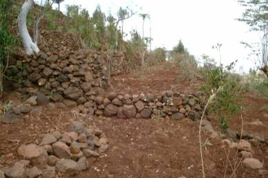
Stone Bunds
Once again these have the effect of slowing down the water flow. They also serve to collect soil.

 |
| Stone lines at approx. 20-30 m intervals |
 |
| Stone bund construction |
Vetiver Grass Erosion Protection
In the workshop so far the emphasis has been on traditional methods of
soil and water conservation that have been used in Africa for hundreds, if not
thousands of years. Vetiver grass has been extensively tested in Africa for at
least the past 40 years and has been found to be highly effective in controlling erosion and retaining soil nutrients.
So the use of vetiver may be classed as a modern erosion protection
measure falling under the heading of biotechnology”. Although vetiver grass is
new to the African continent (originating from India), it is used in what are
actually traditional soil conservation measures (such as hedging and terracing
of slopes).
 |
| Vetiver grass hedge |
In Nigeria, vetiver grass has been tested extensively since the 1970s, and
found to be effective. In the 1980s many
Nigerian federal highway construction projects specified the use of
vetiver erosion protection for roadsides and road embankments. This erosion protection measure was
potentially beneficial for the soil and
water conservation of the surrounding area, because controlling the erosive power of runoff from the road through
sufficient grassing of slopes served to protect the local environment
downstream of road embankment slopes. Unfortunately, many contractors were in
the habit of omitting the vetiver protection and this has led to more
widespread road and local land
degradation.
The reason that vetiver is so effective in soil and water conservation is
due to its massive root system, which can extend to several metres depth into
the soil. This serves to bind together the surrounding soil, making it highly
erosion resistant, whilst the foliage traps sediment and slows the velocity of
erosive overland flow.
The deep root system also serves to increase the soil capacity to absorb
and hold water and therefore vetiver plays a crucial role in helping the more
rapid recharge of groundwater; which is important near water wells and springs in maintaining the community
water supply.
 |
| Vetiver hedging - Ethiopia |
 |
| vetiver |
 |
| Vetiver root system |
Geotextiles
Other modern methods other than the use of vetiver include the use of
geotextiles. These are synthetic & natural materials used mainly in
non-agricultural engineering structures
such as roads and riversides, bridge abutments and roadside drainage
structures to protect against erosion, and are made of materials such as jute
and synthetic fibres .
Geotextiles can be highly useful at roadsides on escarpments and on
other steep slopes to prevent dangerous landslides. However, they are
expensive. They limit erosion as they
protect against rainfall impact and inhibit runoff, and also assist the
establishment of vegetation in taking root and holding the soil together
 |
| Geotextile made from jute (a plant fibre) |
 |
| Slope stabilisation using geotextiles |
 |
| Roadside slope protection using geotextiles |
Water Harvesting
•
Water harvesting, the collection of water directly
from rainfall or from runoff (overland flow) promises to be an efective means
of helping to meeting Africa’s water needs.
•
A recent UN report (2006) estimates that Africa has
the capacity to meet the clean water needs of 1.5 times the Earth’s population
through water harvesting.
•
It is estimated that both Ethiopia and Kenya have the capacity
of meeting the clean water needs of 6-7 times their populations purely through
employing rainwater harvesting techniques.
 |
| Roof construction for rainwater harvesting |
 |
| Runoff rainwater harvesting |
 |
| Runoff rainwater harvested with downstrean pan construction |
•
Reading List
•
Morgan, R.P.C, Soil Erosion & Conservation,
Wiley, 2009 edition.
•
Soil and Water Conservation in Sub-Saharan Africa, IFAD, Rome, 1992
•
A link on “Groundwater and Rural Water Supply in
Africa”: http://www.iah.org/downloads/occpub/IAH_ruralwater.pdf
•
Cabral, A., Return to the Source – Selected
Speeches, Monthly Review Press/Africa Information Service, N.Y. and London,
1973
•
Udealor, A and PO Nwadukwe, On-farm evaluation of
the effect of Vetiver Grass (Vetiveria zizanoides) hedgerow on the soil loss
and yields of the components of Yam/Maize/Cassava intercropping system in
Southeast Nigeria, Nigerian Journal of Soil Science, Vol 17 (2007).
•
Babalola, O. , et al, Use of vetiver grass for soil
and water conservation in Nigeria, http://www.vetiver.org/NIG_SWC.pdf
•
Edem, I.D., et al, Effect of vetiver on
infiltration characteristics of kaolinitic alfisols of Ibadan, South Western
Nigeria, http://iosrjournals.org/iosr-javs/papers/vol1-issue2/J0124549.pdf
Thanks for sharing with us I am happy with your blog so I want to share something with you who is a solar company can be of some help to you and stay with us in future. commercial solar panel systems
ReplyDeleteThanks for sharing with us
ReplyDeletehttps://metsolar.eu/
Excellent overview of solar photovoltaic system installation! Projects like Solar System Installation Neubrandenburg demonstrate how professional planning and quality components ensure long-term performance and clean energy efficiency.
ReplyDelete